Published: March 27, 2007
Last Updated: May 1, 2007
By Richard G. Baldwin
Alice Programming Notes # 120
Part of a series
This tutorial lesson is part of a series designed to teach you how to program using the Alice programming environment under the assumption that you have no prior programming knowledge or experience.
Have some fun
Because Alice is an interactive graphic 3D programming environment, it is not only useful for learning how to program, Alice makes learning to program fun. Therefore, you should be sure to explore the many possibilities for being creative provided by Alice while you are learning to program using these tutorials. And above all, have fun in the process of learning.
In the earlier lesson titled "Setting the Stage Manually, Part 1" (see Resources) I described three real-world scenarios by which a director and stage manager for a stage play or movie can set the stage. I related those three ways to the ways that can be used to set the stage for an Alice program and explained that Alice can be used to model only two of those three ways.
I explained that some people may elect to manually arrange every aspect of the stage, including the positions and the poses of the actors. Other people may elect to manually create the actors, drop them onto the stage (the world), and then write the necessary code to move them to their correct positions, arrange their poses etc. Other people may use some combination of the two. Neither approach is right or wrong. The use of either approach or a combination of the two is simply a matter of preference on the part of the programmer.
In the earlier lesson, I explained how to start from scratch and begin writing a new program. I explained that there are two ways to get objects from the gallery and to place them in the world. I explained how to manipulate the object tree to obtain information about the makeup of each of the objects shown in the tree.
I introduced you to the camera controls and explained how to use them. I also introduced you to the object manipulator buttons and explained how to use them. I showed you how to get a quad view of your world.
I recommend that you open another copy of this document in a separate browser window and use the following links to easily find and view the figures while you are reading about them.
Once you have mastered Alice, I recommend that you also study the other lessons in my extensive collection of online programming tutorials. You will find a consolidated index at www.DickBaldwin.com.
Up to this point, all of our efforts to set the stage have been completely manual, involving such operations as dragging an actor's arm with the mouse to reposition the actor's arm. In this lesson, I will introduce you to methods and show you how to call methods interactively to set the stage without actually running the program.
Everything that appears in an Alice world is an object. Even the world itself is an object.
Every Alice object has, or at least can have:
The current properties, methods, and functions belonging to an object can be exposed by:
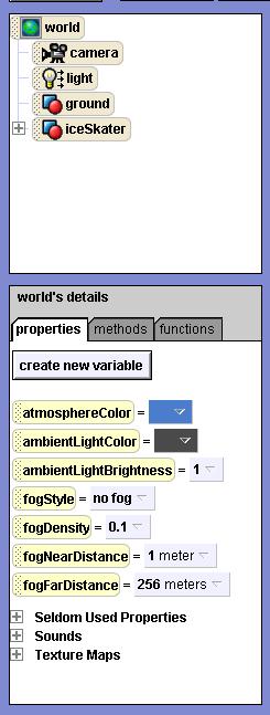
Figure 1. Exposing properties, methods, and functions.
|
|
In Figure 1, the world object was selected in the object tree, and the properties tab was selected in the world's details pane below the object tree.
A property is a value stored in an object that specifies some attribute of the object. In Figure 1, for example, the first property is named atmosphereColor, and as you might expect, it stores the color of the sky.
The other properties shown in Figure 1 specify other attributes, such as fogStyle. (The fogStyle property makes it possible for you to create worlds where the visibility is obscured by something that looks like fog.)
The visual manifestation of the properties
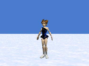
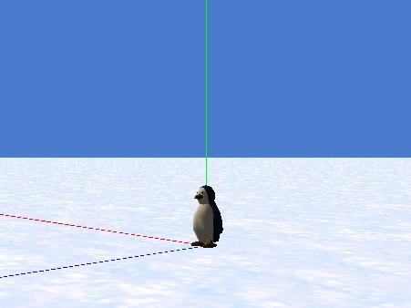
Figure 2 shows the world to which those properties apply. Note that the color of the sky matches the value of the property named atmosphereColor in Figure 1.
Figure 2. The world.
|
|
A method is a set of instructions, grouped together in a special way and given a name as a group. The instructions in the method can be executed by the object to cause it to do something that it is asked to do. In OOP-speak, we say that we can send a message to an object asking it to execute one of its methods.
Methods belonging to the ice skater object
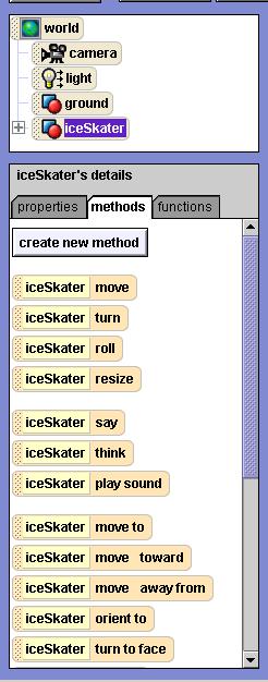
Figure 3 shows some of the methods that belong to the iceSkater object shown in Figure 2.
Figure 3. Methods belonging to the iceSkater object.
|
|
Figure 3 doesn't show all of the methods belonging to that object because the screen wasn't large enough to show them all. In the Alice development environment, the remaining methods can be seen by sliding the scrollbar on the right side of Figure 3.
|
Primitive methods, custom methods, and your new methods
Every object has a group of built-in methods, commonly referred to in Alice literature as primitive methods. Some objects also have special methods in addition to the primitive methods that are often called custom methods. In addition to those methods, you can create your own methods by clicking the button that reads create new method in Figure 3. Once you click that button, you will be walked through a dialog by which you can define all of the behaviors of your new method.
|
I told you earlier that a method is a set of instructions, grouped together in a special way and given a name as a group. A function is also a set of instructions, grouped together in a special way and given a name as a group.
What is the difference between a method and a function?
Unlike Alice, not all programming languages distinguish between methods and functions. In Java, for example, there is no distinction between methods and functions. In fact, the term function is rarely seen in the Java literature, and when it is seen, it is probably a holdover from C and C++ terminology. However, Alice does make that distinction. According to the Alice terminology, a method causes an object to perform an action such as to move in a prescribed direction for a specified distance. A function returns a value, such as the width of the object to which the function belongs.
Functions belonging to the ice skater object
Figure 4 shows some of the functions that belong to the iceSkater object.
Figure 4. Functions belonging to the iceSkater object.
|
|
Will concentrate on calling methods interactively
In the lesson titled "Learn to Program using Alice, Setting the Stage Manually, Part 1" (see Resources) I taught you how to use the object manipulator buttons in conjunction with the mouse to manipulate objects. If you recall, in Figure 11 of that lesson, I showed you an image in which I had used the mouse to pose the Coach object to make it look as if he was demonstrating how to kick a football.
Sometimes it can be very difficult to move the various parts of an object in the way that you want to move them using the mouse. The remainder of this lesson will teach you how to call methods interactively to manipulate objects as an alternative to using the mouse for that purpose.
Writing program code
Later on, when you write a program to animate a world, a very large portion of the code that you write will call methods on objects (including the objects that are parts of larger objects) to cause them to execute some action, such as to move, rotate, change color, become invisible, etc.
You can write the code to cause those methods to execute in sequential order, or you can write code to cause them to execute concurrently. You can write code to cause them to execute repeatedly, and you can write code to cause the methods that are selected for execution to depend on some other circumstance (selection). All of those possibilities will be topics of future lessons that teach you how to write animation code.
It is also possible to call methods interactively, one at a time, during the development process. This provides at least the following two benefits:
I will explain both of these processes later in this lesson, but before I get to that, there is another important topic that I need to explain. That topic has to with the position of objects in 3D space.
Most people who write programs that manipulate objects in 3D space think in terms of a 3D coordinate system where a specific point or location in that coordinate system is specified by three coordinate values. Very frequently the axes are thought of as a horizontal axis, a vertical axis, and an axis that is perpendicular to a plane that goes through the horizontal and vertical axes. Typically those axes are thought of as being represented symbolically by X (horizontal), Y (vertical), and Z (perpendicular to X and Y).
|
The folks at Carnegie Mellon went to great lengths to exclude abstract mathematical concepts from the Alice programming environment (such as a point in space). Directions in Alice are typically referred to as FORWARD, BACKWARD, RIGHT, LEFT, UP, and DOWN, rather than by using the more abstract mathematical concepts that are common in other 3D programming environments.
There is good news and bad news in keeping things simple to that extent. While such an approach may be, and probably is, more intuitive to students, in some cases, the approach makes it more difficult to do some of the things that need to be done.
Adding objects to a new world
Take the case of adding objects to a new world. A person who is more inclined towards art rather than computer programming might simply add objects to the world and drag and rotate them with the mouse until they "look good." While that may be okay for art, it is not a very good approach for writing animation programs such as game programs.
|
Typically animation programs that deal with the movement of multiple objects in a world (such as a game program) need to know at all times the position and orientation (viewpoint) for every object in the world. (For example, the program often needs to make certain that objects don't collide with one another, or perhaps make certain that they do collide with one another, depending on the nature of the objects.) As a result, such a program probably needs to be able to establish an absolute viewpoint for every object in the world when the program starts running.
A center point and orthogonal coordinate axes
As you learned in the earlier lesson titled "Learn to Program using Alice, Objects in 3D Space" (see Resources), every object in an Alice world has a center point. (In other 3D programming environments, this would probably be called the origin of the coordinate system for the object.)
Where are new objects located?
Obviously, if you drag an object from the gallery to the world, it may end up anywhere relative to the center point of the world. Its position depends entirely on where you drop the new object in the world.
|
Testing the alignment of new objects in the world
I know of no easy way to prove whether or not the center point for the ground is aligned with the center point for the world, but it is easy to show that the center points for many objects don't automatically align with the center point for the world or with the center point for the ground.
Do the following and you will see what I mean.
Ice skater and parking meter will be at different positions
When you view the world, it should be obvious that the two objects didn't end up at the same position on the ground. (See Figure 5 for example.) Therefore, even if the center point of one of the objects is aligned with the center point of the world, both of them can't possibly be aligned with the center point of the world.
Expose the axes for the ground
To make this even more visually obvious, click somewhere on the snow to cause the red, green, and blue axes for the ground to become visible. Recall that the green axis points up relative to the viewpoint of the ground, the red axis points to the right relative to the viewpoint of the ground, and the blue axis points to the front relative to the viewpoint of the ground.
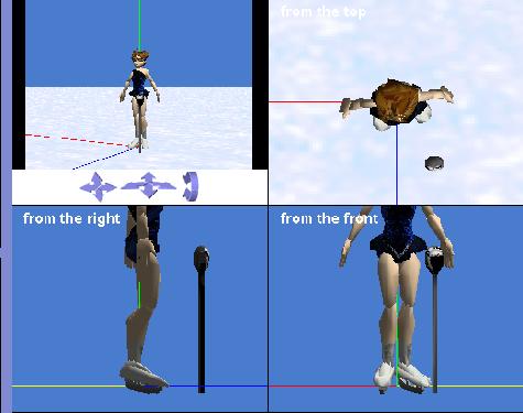
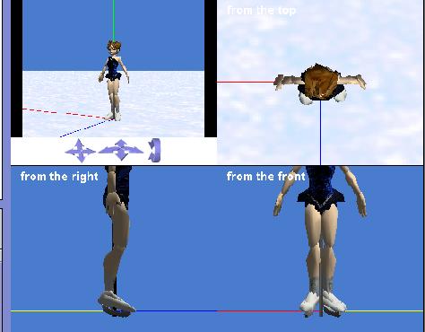
Now select the quad view radio button in the upper right portion of the screen. The result should look something like that shown in Figure 5.
Figure 5. Two objects not aligned at center point of the world.
|
|
As you can see, it appears that the IceSkater object was placed at (or near) the center point of the ground, (which may or may not be aligned with the center point of the world). However, the parking meter was placed a little in front of, and to the left of the ice skater.
Setting the display style preference
Let's take another side trip and discuss how information is displayed in Alice. Depending on how you set your preferences, you can cause various types of information to be displayed in any one of three different formats in Alice.
|
My recommendation that you use Java Style in Color, simply because that will better prepare you for continuing your effort to learn programming in some other language such as Java, C#, or C++. Unfortunately, when you set this preference, the Alice system doesn't always remember it. Sometimes it reverts to Alice Style somewhere down the road when you start Alice running.
Procedure for setting the preference
To set this preference,
You will be notified that "You will have to restart Alice in order for these settings to take effect."
Click OK and then Exit and restart Alice.
On the other hand, if the button already reads Java Style in Color, just click Cancel to terminate the dialog without changing anything.
Creating an initial alignment
Now let's get back to what I was discussing before I went off on that side trip having to do with the display style.
Here is what I recommend that you do at the beginning of every animation program to create an initial alignment of all the objects in the world. In order to carry out this procedure as you are manually setting the stage, you will be interactively executing some of the methods that belong to the objects. Later on, you will learn how to include the same steps in the program code if you prefer not to set this part of the stage manually.
Set the alignment for each object
Following the procedure given above should ensure that the viewpoint of the ground is properly aligned with the viewpoint of the world (in case it wasn't already aligned). For the next step, you need to do essentially the same thing for every object that you have added to the world. For example, using obj to represent an object:
|
As you execute that procedure once for each object and you watch the quad view, you should see the objects adjust their positions and orientations so as to be aligned with the world. This will also cause the objects to be aligned with the ground which was aligned with the world earlier.
Aligning the ice skater and the parking meter
Figure 6 shows the result of executing this procedure on the ground, the ice skater, and the parking meter.
Figure 6. Two objects aligned at center point of the world.
|
|
As you can see in Figure 6, the ice skater and the parking meter are now located at the same point on the ground, and the outstretched hands of the ice skater line up with the red axis. Compare this with Figure 5 where the parking meter is quite a distance from the center point on the ground, and the ice skater's outstretched hands do not quite line up with the red axis.
Is the parking meter properly oriented?
Although you can't tell anything about the orientation of the parking meter in Figure 6, I made the ice skater temporarily invisible so that I could see the parking meter by itself. The widest dimension of the head on the parking meter lines up with the red axis, which strongly suggests that it is aligned with the ground and the world.
Ice skater and parking meter have had a collision
As you can see in Figure 6, there is nothing to prevent two objects from occupying exactly the same space in Alice (and in most other 3D environments as well). This may be another good reason why an animation program would need to keep track of the viewpoints of all its objects; to avoid collisions between objects.
Some conventions regarding positive and negative directions
Now that we know exactly where the two objects are located, we are prepared to interactively call methods on the objects to change their viewpoints to the desired viewpoints for setting the stage. Before doing that, however, we need to adopt some conventions as to what constitutes positive and negative directions of motion. We will adopt the following conventions:
Notation for a point in space
This will make it possible for me to refer to the coordinate axes as red, green, and blue, and to write a position in 3D space using the following format where nn represents a numeric value:
Rnn,Gnn,Bnn
For example, R3,G4,B-5 represents a point that is 3 meters to the right of, 4 meters above, and 5 meters behind the center point of the world.
A shorthand notation for describing an interactive method call
I showed you earlier how to go about calling methods on an object interactively. At this point, I am going to adopt a shorthand notation to describe an interactive method call. This will make it possible for me to write the details of such a method call on a single line rather than requiring multiple lines as was the case above.
|
An example of the shorthand notation
I will use an ellipsis (...) to represent the contents of a pair of parentheses, and will use a backward slash "\" to represent progression from one menu to the next. When written in this format, the earlier set of instructions would be written as:
obj.setPointOfView(...)\the entire world
where obj represents ground and ... represents the contents inside the parentheses in the menu item.
Setting a new viewpoint for the ice skater
Assume that the script calls for the ice skater to be at the following coordinates when the curtain rises:
R1,G2,B-3
Also assume that the script calls for the ice skater to be oriented such that she is facing in a direction that is 30 degrees to the left of the blue axis belonging to the ground.
|
obj.move(...)\RIGHT\1
obj.move(...)\UP\2
obj.move(...)\BACKWARD\3
obj.turn(...)\LEFT\30/360
Let's see what we accomplished
Figure 7 shows the result of making these four method calls and then clicking the ground to expose the center point and the axes for the ground.
Figure 7. Result of making interactive method calls to change skater's viewpoint.
|
|
A visual reference may be helpful
The parking meter hasn't been moved, so it is still located at the center point of the ground and the center point of the world. It might be helpful to create a reference object at the center point of the world, (such as the parking meter in Figure 7), to provide a visual reference while you are setting the viewpoints of the other objects. When it is no longer needed, simply right-click on the reference object and select delete to remove it from the world.
Although it is difficult to determine exactly where an object is located in 3D space simply by looking at a 2D picture, the center point of the ice skater in Figure 7 has been moved to a position that is one meter to the right of, two meters above, and three meters to the back of the center point for the ground, which is aligned with the center point of the world. Thus, she also has that same viewpoint relative to the parking meter.
Useful methods for manually setting the stage
Here is a list of methods that belong to almost all objects that you may find useful in manually setting the stage:
These same methods will also prove to be useful in future lessons when we elect to set the stage by executing program code. The behavior of these thirteen methods, as well as the behavior of the remainder of the twenty Alice primitive methods are explained and illustrated in Appendix A (see Resources).
A standard repeatable viewpoint for the camera
As I explained earlier, you can change the picture in the camera's viewfinder in either of two ways:
|
One of the common problems that arise when you are setting the stage manually is that you elect to use the camera controls to change the camera's viewpoint in order to get a better look at an object. Having done that, you may find that you are unable to manually change the viewpoint back to the original position and orientation.
However, you can interactively call methods on the camera object to establish a known viewpoint for the camera in a totally reliable way.
Relating the world to the points of the compass
In order to for me to use commonly understood terminology to explain what I am talking about, let's assume that the direction indicated by the blue axis in Figure 8 points toward the south.
Figure 8. The three axes belonging to the ground.
|
|
|
Changing the camera's viewpoint in a reliable, repeatable way
Now assume that you want to relocate the camera to a position that is ten meters away from the center point of the ground, located 1.5 meters above the ground, and oriented toward the northwest. You can accomplish this by interactively calling the following methods where obj represents the camera.
Call the setPointOfView method
The first instruction in the above list will relocate the camera to the center point of the ground matching the viewpoint of the ground. This will cause the camera to be located at ground level facing along the blue axis (south). The picture that you see when you do this isn't very interesting so I didn't show it here.
Call the turn method
The second instruction listed above will turn the camera so that it is oriented towards the northwest. In other words, the method call will rotate the camera to the right around the green axis in Figure 8 by 3/8 of a revolution or 135 degrees.
Call the moveAwayFrom method
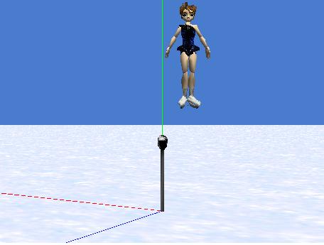
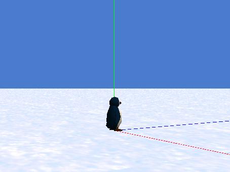
The third instruction listed above will move the camera backwards by ten meters along a line from the northwest to the southeast. The picture that you see following the execution of this instruction is interesting, and is shown in Figure 9.
Figure 9. Camera at ground level, ten meters from center point of world.
|
|
At this point, the camera is still at ground level. The horizontal white line in Figure 9 represents the ground. (Alice worlds are hollow with the ground being merely a thin shell.)
Call the move method
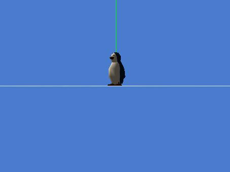
Finally, the fourth instruction listed above will raise the camera by 1.5 meters above the ground without changing its orientation, thereby producing the picture shown in Figure 10.
Figure 10. Final viewpoint of the camera.
|
|
In Figure 10, the camera is ten meters away from the center point of the ground, is 1.5 meters above the ground, and is oriented toward the northwest.
Three interesting parameters
There are three interesting parameters highlighted in boldface in the list of four instructions:
The last two of these parameters are generally self explanatory. However, the first parameter deserves some explanation.
The rotation angle
Although it may not make a lot of sense to think in terms of the ground facing in a particular direction, if the viewpoint of the ground matches the viewpoint of the world, then by default the blue axis belonging to the ground runs from the center point toward the south.
If the camera has the same viewpoint as the ground (see the first instruction above), then the camera is located at the center point of the ground and is also oriented toward the south.
If we rotate the camera by 135 degrees to the RIGHT, (or rotate it by 225 degrees to the LEFT), the camera will be oriented toward the northwest.
Similarly, rotation by 180 degrees in either direction will cause the camera to be oriented to the north. Other rotation angles will cause the camera to be oriented in other directions.
The important point
The exact position and orientation of the camera from this example is not the important point in this discussion. The important point is that by interactively calling various methods on the camera, you can cause it to have any viewpoint that suits your needs. If you move it manually and need to restore it to a known viewpoint, all you need to do is to interactively call the same set of methods again.
The right-hand rule
An important part of setting the stage is posing the actors. For example, one actor may need to be posed with one arm down to her side with the other arm slightly elevated and bent at the elbow. Other actors may need to be posed in different ways.
Objects are composed of objects
As you learned in an earlier lesson, many Alice objects are actually composed of smaller objects such as upper body, arm, leg, foot, hand, etc. Every object (including the objects that are used to construct other objects) has its own center point and its own coordinate system. By selecting the object, that coordinate system can be exposed showing three orthogonal axes colored red, green, and blue as shown in Figure 10.
Rotating objects in 3D space
Typically, in order to arrange the various parts of an object, you need to rotate each object around one or more of the axes belonging to that part.
Here are some rules for rotating an object around its different axes.
You need to understand the directions of the axes
In order to call the methods that are required to move the objects that make up a larger object (arms, legs, etc.) either interactively or in code that will be executed in an animation sequence, you must know the direction of each of the axes belonging to that object. Often, those axes are difficult to see. Sometimes you can't see any of the axes without making the object invisible. Sometimes you can see one, but in order to see two or more, you must make the object invisible. Sometimes you can see two, but not all three, and sometime you can see all three.
For the case where you can see any two of the three axes, but you can't see the third axis, you can always figure out what the direction of the missing third axis is. A handy aid in doing this is something called the right-hand rule.
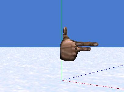
A picture of the right-hand rule
Consider the picture of a right hand shown in Figure 11. Assume that you hold your right hand such that the index finger and the middle finger are at right angles to one another (see Figure 11), and your thumb is at right angles to both of the fingers. If you point your thumb along the green axis and your index finger along the red axis as shown in Figure 11, your middle finger will point along the blue axis. Using this visual aid, if you can see any two of the axes belonging to an object, you can easily figure out the direction of the third axis.
Figure 11. Illustration of the right-hand rule.
|
|
As an exercise, see if can use an object of the RightHand class in the People gallery to replicate the picture shown in Figure 11.
The airplane rule
Another aid that may make it easier for you to visualize the axes belonging to an object is the airplane rule. (See Figure 3 in the earlier lesson titled "Learn to Program using Alice, Objects in 3D Space." (See Resources.)
Mentally place an airplane at the center point of the object with the fuselage parallel to the blue axis and the front of the airplane pointing in the direction of the blue axis. Make the right wing parallel to the red axis pointing in the direction of the red axis. Then the green axis will be protruding from the top of the pilot's head.
Put an airplane in the picture
In order to cause an object to rotate around the correct axis, you must determine whether to turn the object or roll the object. You must also discern among RIGHT, LEFT, FORWARD, and BACKWARD. Sometimes this can be a very difficult decision.
A good way to do this is to imagine a small airplane in the picture. Align the airplane parallel to the blue axis causing the green axis to protrude from the top of the pilots head. Orient the airplane so that the pilot is looking in the direction of the blue axis when she is looking forward. Cause the right wing of the airplane to be pointing in the direction of the red axis. Assume that the object is firmly attached to the airplane and will experience the same motion as the airplane.
Yaw
To cause the airplane (and hence the attached object) to turn to the right or left, you must call the turn method and specify RIGHT or LEFT as a parameter. This will cause the airplane to rotate around the green axis.
Pitch
To cause the airplane to pitch the nose down and dive toward the ground, you must call the turn method and specify FORWARD as a parameter. To cause the airplane to pitch the nose up and climb, you must call the turn method and specify BACKWARD as a parameter. This will cause the airplane to rotate around the red axis.
Roll
To cause the right wing to tilt downward, you must call the roll method and specify RIGHT as a parameter. Similarly, to cause the left wing to tilt downward and the right wing to tilt upward, you must call the roll method and specify LEFT as a parameter. This will cause the airplane to rotate around the blue axis.
Two or more actions are often required
Often, you will need to take two or more of the above actions in sequence to accomplish the total motion that is needed. Just remember that each time you take any of the above actions, two of the three axes that belong to the object will change direction, and you must change the viewpoint of your imaginary airplane accordingly.
Getting back to the movement of body parts
Throughout this discussion, I have been hinting that I would teach you how to cause the individual body parts of an actor to move appropriately. That time has come.
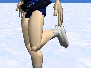
Assume that we would like to cause the ice skater shown in Figure 2 to lift the lower part of her left leg towards her back and cause her toe to point away from her. This can be difficult unless we have memorized the directions of the red, green, and blue axes at her knee and ankle joints (see "Learn to Program using Alice, Objects in 3D Space" in Resources). Since I don't have that information memorized, I will need to take a closer look at the knee and ankle joints to learn the directions of the axes.
Rotation around the axes
I have explained that you can perform the following operations on an object:
Even if you have memorized the initial directions of the three axes for a given joint, when you perform a rotation operation on that joint, two of the three axes will end up pointing in a different direction. This can make it difficult to figure out how to make the next move on the same joint. For example, quite a lot of work would be required to figure out how to:
Exposing the axes belonging to the lower leg
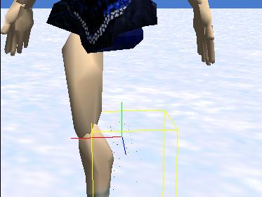
Figure 12 shows how I exposed the axes in the ice skater's left knee. The lowerLeg object belonging to the leftLeg object must be rotated around the red axis to accomplish the first step in the desired motion described above, lifting the lower part of her left leg toward her back.
Figure 12. Axes in the left knee exposed.
|
|
The steps for exposing the axes
Here are the steps that I went through to produce the image in Figure 12.
|
Having done that, I concluded that the green axis points up through the left thigh, the red axis points out of the left knee toward the ice skater's right knee, and the blue axis points out of the left knee toward the front of the ice skater.
How must the lower leg be rotated?
From the above information, I concluded that I needed to rotate the left lowerLeg object around the red axis so as to cause the blue axis to tilt downward (cause the imaginary airplane to go into a dive) in order to make the foot lift upward. To accomplish this, I needed to call the turn method on the lowerLeg object, turning FORWARD one-fourth of a revolution.
Make the left leg totally visible
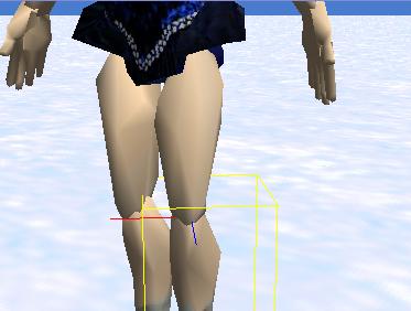
The next step, before performing the rotation, was to restore all the parts of the left leg to their normal condition by returning the property values to their original values. That got me back to the image in Figure 13 where you can see the red and blue axes, but you can't see the green axis.
Figure 13. Red and blue axes of lower left leg showing.
|
|
(Note that because I could see the blue axis and the red axis in Figure 13, I could have used the right-hand rule or the airplane rule described earlier to deduce the direction of the green axis and could have saved myself the work that was required to produce the image shown in Figure 11.)
Call the turn method
The next step is to call the turn method on the lowerLeg object that belongs to the leftLeg object. To do this, right click on the lowerLeg object that belongs to the leftLeg object in the object tree. Then make the following selections from the popup menus that appear:
obj.turn(...)\FORWARD\90/360
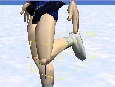
Now you can use the mouse to turn the ice skater a little to her right to make her leg more visible, producing the image shown in Figure 14.
Figure 14. Knee bent and lower leg lifted.
|
|
What about the axes?
Now take a look at Figure 15. Figure 15 is the same as Figure 14 except that the lowerLeg was selected to cause the new directions of the axes to be exposed.
Figure 15. Left lower leg with axes showing.
|
|
Note that the green axis no longer points up through the thigh. Rather, it now points out toward the front. Similarly the blue axis no longer points out toward the front, but now points down. The red axis still points toward the right knee. Recall that I told you in an earlier lesson that the axes move and rotate with the object to which they belong.
Pointing the toes toward the back
Now we need to rotate the foot in order to make the left toes point out behind the skater. We need to investigate the ankle and determine the direction in which each of the three axes is pointing in order to know whether to turn or to roll and in what direction.
The axes belonging to the foot
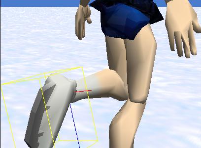
Figure 16 shows the skater turned so as to expose the red and blue axes belonging to the foot. The airplane rule tells us that the green axis extends through the calf of the leg toward the knee.
Figure 16. Red and blue axes for the foot exposed.
|
|
By embedding an imaginary airplane into the ankle joint properly aligned to the red and blue axes, and firmly attaching it to the foot, we can deduce that if we cause the nose of the airplane to pitch downward, that will cause the toes to point away from the skater. That is the motion that we want.
Rotate the foot around the red axis
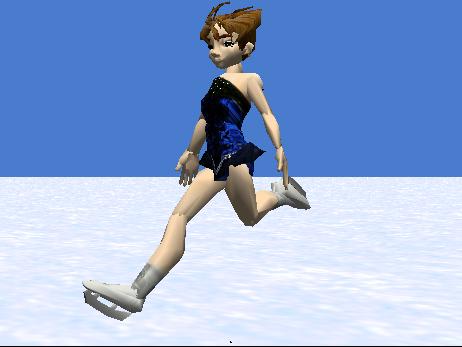
If you turn the foot FORWARD by 0.125 revolution and change the viewpoint of the skater, you should get an image similar to that shown in Figure 17.
Figure 17. Skater with toes pointing behind her.
|
|
You will probably agree that the new position for the foot shown in Figure 17 looks a little more natural (or at least a little more graceful) than the position of the foot in Figure 15.
(To turn by 0.125 revolutions, select other when you get to the amount panel. That will bring up a keypad image allowing you to enter the decimal value as described earlier.)
Working out the animation steps before writing code
I told you earlier that another benefit of being able to interactively call methods on objects is the ability to create short animation sequences and manually execute them one step at a time to see if they do what you want them to do before you write the steps into your animation program.
Suppose, for example, that you want to animate the ice skater to cause her to raise her leg and point her toes away from her body as shown in Figure 17, and then to execute the reverse of that motion, ending up with both skates on the ice. You now know the sequence of method calls required to get from the standing position in Figure 13 to the position shown in Figure 17. You should be able to figure out the sequence of method calls that can be used to reverse that motion, and you can test them one step at a time to confirm that they behave as you expect.
Incorporating the method calls in animation code
Having done that, once you learn how to write program code to animate the process in future lessons, you can write code to call the same methods in the same order to achieve the desired result.
Concurrent operation
Although you can't do this interactively, once you incorporate the method calls in program code, you have the option of causing the methods to execute concurrently. For example, in program code, it would not be necessary to cause the ice skater to first raise her leg and then point her toes. You could cause her to be rotating her foot around her ankle joint at the same time that she is rotating her lower leg around her knee joint. That would look more natural than executing the two motions in sequence.
|
Not a trivial capability
The ability to make the method calls interactively is not a trivial capability in view of the inherent difficulty of deciding when to turn and when to roll, and whether to specify LEFT, RIGHT, FORWARD, or BACKWARD to achieve the desired motion. Sometimes you need to be able to examine the red, green, and blue axes belonging to an object to make the correct decision among those alternatives, and you can't easily examine the axes in a running animation program.
Animating a world
For every sequential step in the animation of a world, you must deal with translation and rotation requirements for every object. In other words, for those objects that move, you must make method calls to specify the direction (UP, DOWN, RIGHT, LEFT, FORWARD, and BACKWARD) as well as the distance that the object is to move.
For those objects that rotate, you must make method calls to specify the yaw, pitch, and roll required for the object.
What about objects that belong to other objects?
As you are now aware, many objects are composed of other objects. Fortunately, it isn't necessary for you to individually control the motion of every object that is a part of a larger object. When you control the motion of the larger object, the objects that belong to it will go along for the ride. However, if needed, you can control the motion of those component objects in addition to the motion of the object to which they belong. For example, you could cause the ice skater to glide across the ice in a forward direction and at the same time cause her to raise her lower leg and point her toes behind her, in effect skating on one foot.
The main theme
This was a long lesson that covered a large number of important concepts. The main theme of this lesson was to teach you how to interactively call methods on objects, primarily to use that process as an alternative to moving and rotating objects with the mouse while setting the stage. I also explained how this capability can be used to test short animation sequences one step at a time before committing them to animation code.
Properties, methods, and functions
I taught you about the properties, methods, and functions that belong to each object. I explained how to distinguish between methods and functions. Following that, I concentrated primarily on calling methods interactively, but I also made some use of properties as well.
Exposing the red, green, and blue axes
I explained the need, and showed you how to expose the red, green, and blue coordinate axes belonging to an object in order to be able to execute the proper amount of yaw, pitch, and roll on that object during the animation process.
Viewpoint
I explained the concept of viewpoint as used in the Alice programming environment.
Initial alignment of the world
I taught you how to "zero out" the world by causing the viewpoints of all of the objects in the world to be aligned with the viewpoint of the world. I recommended that you do this at the beginning of every program, whether you are setting the stage manually or are setting the stage in program code.
Setting display preferences
I taught you how to set your display preferences to cause certain text material to be displayed in Java style rather than Alice style. I recommended that you do this because it will better prepare you to move on to languages such as Java, C++, and C# later.
The potential for collisions
I taught you a little about collisions and explained that an animation program normally needs to know the viewpoints of all objects in order to properly deal with collisions.
Notation conventions
I established several sets of notation conventions that I used to reduce the amount of text required to describe a position or a method call.
Making interactive method calls
I taught you how to make interactive method calls to set the viewpoint for an object.
I provided a list of methods that may be useful for making interactive method calls to set the viewpoint of an object.
A repeatable viewpoint for the camera
I explained the reasons why, and then taught you how to set a repeatable viewpoint for the camera. In so doing, I related the directions in the world to the point on a compass.
The right-hand rule and the airplane rule
I taught you about the right-hand rule and the airplane rule as two different aids for visualizing the effects of causing an object to undergo yaw, pitch, and roll.
Controlling the motion of body parts
I showed you how to interactively call methods to control the motion of the body parts of an actor, using the lower portion of the left leg and the left foot of an ice skater as an example. In the process, I showed you how to use properties to cause a body part to become invisible in order to expose the red, green, and blue axes belonging to the object.
A short preview of animation
In the way of a preview, I explained some of the things that you will encounter once you start incorporating method calls in executable animation code.
The purpose of this series is not to teach you how to be an animator. Rather, the purpose is to teach you how to be a programmer. In the next lesson, I will begin the serious business of teaching you fundamental programming concepts. In that and subsequent lessons, I will use animation examples to illustrate the use of such fundamental concepts.
Use interactive method calls on an ice skater object and the camera to produce the pose and the camera viewpoint shown in Figure 18. Save your world in a file named Alice120LabProj.a2w and be prepared to deliver it to your instructor in whatever manner the instructor specifies.
Figure 18. Required program output for lab project.
|
|
Copyright 2007, Richard G. Baldwin. Faculty and staff of public and private non-profit educational institutions are granted a license to reproduce and to use this material for purposes consistent with the teaching process. This license does not extend to commercial ventures. Otherwise, reproduction in whole or in part in any form or medium without express written permission from Richard Baldwin is prohibited.
Richard has participated in numerous consulting projects and he frequently provides onsite training at the high-tech companies located in and around Austin, Texas. He is the author of Baldwin's Programming Tutorials, which have gained a worldwide following among experienced and aspiring programmers. He has also published articles in JavaPro magazine.
In addition to his programming expertise, Richard has many years of practical experience in Digital Signal Processing (DSP). His first job after he earned his Bachelor's degree was doing DSP in the Seismic Research Department of Texas Instruments. (TI is still a world leader in DSP.) In the following years, he applied his programming and DSP expertise to other interesting areas including sonar and underwater acoustics.
Richard holds an MSEE degree from Southern Methodist University and has many years of experience in the application of computer technology to real-world problems.
-end-