Baldwin walks you step-by-step through the design, specification, coding, testing, and debugging of a complete Alice animation program. The animated presentation is subdivided into two acts and several scenes, with some special effects being used to emphasize the transitions between scenes.
Last updated: August 26, 2007
By Richard G. Baldwin
Alice Programming Notes # 130
Part of a series
This tutorial lesson is part of a series designed to teach you how to program using the Alice programming environment under the assumption that you have no prior programming knowledge or experience.
Have some fun
Because Alice is an interactive graphic 3D programming environment, it is not only useful for learning how to program, Alice makes learning to program fun. Therefore, you should be sure to explore the many possibilities for being creative provided by Alice while you are learning to program using these tutorials. And above all, have fun in the process of learning.
In the previous lesson titled "Learn to Program using Alice, Your First Alice Program" (see Resources), I presented and explained six programs that use program code to replicate (and in some cases to improve upon) the things that you accomplished using interactive method calls in an earlier lesson.
The first four programs emphasized setting the stage by executing program code. Each of these programs accomplished essentially the same thing, but each program illustrated better program design than the ones before it.
The last two programs emphasized improvements in the animation process, culminating with the use of concurrent programming.
In that lesson, I concentrated on the mechanics of writing simple Alice programs. In this lesson and future lessons, I will teach you the finer points of programming including such things as program design, program logic, etc.
I recommend that you open another copy of this document in a separate browser window and use the following links to easily find and view the figures and listings while you are reading about them.
Once you have mastered Alice, I recommend that you also study the other lessons in my extensive collection of online programming tutorials. You will find a consolidated index at www.DickBaldwin.com.
A step-by-step tutorial
In this lesson, I will walk you step-by-step through the design, specification, coding, testing, and debugging of a complete Alice animation program. This animation tells the story of a family of three penguins (mama, papa, and baby), who are wandering aimlessly on the ice when there is a sudden noise and a hole appears in the ice.
The papa penguin decides to go for a swim, so he walks to the hole, shows off his Olympic diving skills, and dives through the hole making a loud splash. The mama and baby penguins walk to the hole and look in to see if they can see papa penguin.
A two-act play
The presentation is subdivided into two acts and several scenes, with some special effects used to emphasize the transitions between scenes.
Emphasizes the design and organization
The emphasis in this lesson will be on the design and organization of a computer program. The actual code that implements the program will include some important programming concepts that I haven't previously covered in this series of tutorials. In some of those cases, I will defer the explanation of the code to future lessons that concentrate on those concepts.
Although this might sound like motherhood and apple pie, you should plan and design your program before you start writing code. Although it isn't usually necessary to design the entire program down to the last detail, you should at least know what the behavior of the major parts of the program will be. (You can usually defer some of the lower-level details until later in the development cycle.)
Many professional programmers use a process often referred to as the program development cycle. Although there are different variations on the concept, most of those variations include the following steps:
Although this should be fairly obvious, I will make a few comments on each of the steps just to clarify them.
Understand the requirements
There is a famous saying that goes something like "If you don't know where you are going, any road will get you there." The message is obvious. Make certain you know what your customer expects of the program before you begin designing and coding it. Otherwise, you are likely to expend a lot of time, energy, and cost only to end up with an unhappy customer.
Depending on the nature of your customer, this understanding may be easy, or it may be difficult to come by. Some customers know exactly what they expect and they know exactly how to express it. Other customers frequently don't know what they want, or don't know how to express it, or both. In that case, you may be pressed to the limits of your diplomatic skills in trying to come to a true understanding of what the customer expects.
Regardless of how difficult it may be to come to that understanding, do it. You will be glad if you did, and possibly sorry if you didn't.
Design the program (down to a reasonable level of detail)
There are many ways to design a program. Some software designers use flowcharts. Others use pseudocode. Some designers use a combination of the two. Some object-oriented program designers use other techniques that are especially suited to object-oriented design.
In this lesson, I will illustrate a design technique resembling something that is often referred to as top-down design. I will supplement that with program specifications. However, I won't try to teach you to be a software designer. I'm confident that if you go to Google and search for flowchart, pseudocode, "object-oriented design", "top-down design", "software design", and similar keywords, you will find material on this topic that is much better than I am capable of providing. I recommend that you do just that.
Code the program
Once you have designed your program (down to the appropriate level of detail), you can begin coding it. Once you finish coding it, you can test it.
Should be able to completely code and test during each cycle
You should make certain that you have elected to design to a level of detail that can be completely coded and completely tested. In other words, at every stage in the program development cycle, you should be able to code and test to the level of detail to which you have done the design. If that isn't the case, you need to rethink the level of detail to which you are designing, coding, and testing during that cycle.
Will code in Alice
In this lesson, I will show you how to code the program in Alice and how to test the program in the Alice development environment. Other lessons on my website illustrate how to code programs in Java, C++, C#, etc.
Test the program
The purpose of testing a program is to confirm that the behavior of the program meets the customer's expectations, and if it doesn't, to prepare you to explain how and why it fails to meet those expectations (sometimes the customer's expectations prove to be unrealistic relative to the circumstances in which the program is used.). It should be noted that if the program fails to meet the customer's expectations, you may be in for a long and unpleasant negotiation. Therefore, it will behoove you to work at managing the customer's expectation back at the first stage of the entire process.
Different programs, written in different programming languages and environments can be, and often must be tested in many different ways. However, you don't have very many testing options in Alice. Since the primary behavior of an Alice program is to animate characters in a 3D world, testing of Alice programs consists mainly of running all or parts of the program and observing the action to see if the character behave as they should.
|
Surprise! The program may fail to meet the customer's expectations.
The next step is commonly referred to as debugging. Debugging is the process of finding and correcting those programming errors or circumstances that prevent the program from performing correctly.
Debugging can be very difficult. Different programming environment offer different tools to be used for debugging. Unfortunately, Alice doesn't offer much in this regard beyond the ability to disable and enable statements in an attempt to find the statement or statements that are causing the problem.
Go back to the top if necessary (design in more detail)
Sometimes at this point, it is necessary to go all the way back to the top of the loop and try to convince the customer that she should modify her expectations. This is often not a pleasant experience.
Sometimes it is concluded that the customer's expectations are still okay, but there is a problem with the original design. In that case, it may be necessary to modify the design and take another pass at the coding, testing and debugging steps to achieve the desired results.
Frequently, as will be the case with the program in this lesson, the first design did not include all of the details necessary to code and test the entire program. In that case, once you have coded and successfully tested the design at its current level of detail, the next step is to go back to the top and supplement the existing design with more design details.
Sometimes for very complex programs, it is necessary to repeat this cycle several times in order to finally get it right. This cycle is what is commonly referred to as the program development cycle.
Can apply to the sub-tasks as well
This development cycle can, and often is applied to the programming project as a whole. It is also common practice to subdivide a large programming project into a series of smaller tasks and to apply the program development cycle to those smaller tasks. In addition to the advantages of applying the program development cycle to the project as a whole, it is often beneficial to apply it to the individual tasks.
What's next?
During the remainder of this lesson, I will illustrate different facets of this development cycle by walking you through a complete Alice programming project.
The programming project
The project is an animated sequence to be used as a TV commercial designed to entice people to vacation in Antarctica. (I doubt however that it will be very effective in that regard.)
A two-act play
As it turns out, the organizational approach that is often used for movies and stage plays lends itself very nicely to the creation of animated sequences in Alice. We will subdivide the entire program into two acts. The first act will be subdivided into two scenes. The second act is small and won't need to be subdivided into scenes.
Three segments in each scene
Each scene in Act 1, (as well as Act two as a whole) will be subdivided into three segments:
In addition, there will be an opening segment and a closing segment for the program as a whole.
Why three segments?
The segments will be used to reduce the clutter in the code. The use of segments will also make the program easier to test (and to debug if need be) and to modify later if needed.
Generally speaking the setup segments will be the repository for the code necessary to get the actors and the props ready for "lights, camera, and action." The setup segments along with the closing segments will also serve as the repository for the code required to create the special effects that are used to transition from one scene to the next.
The action segments will serve as the repository for the code that carries the story line.
A description of the customer's expectations
We will begin with a brief written description of the customer's expectations (the overall program specifications) as shown in Figure 1. As we continue looping through the program development, we will add more detail to the program specifications. This is often referred to as a process of stepwise refinement.
Figure 1. Top-level program specifications.
|
Top-level program specifications. Act 1, Scene 1 Act 1, Scene 2 Act 2 Supplemental Information 3D text appears on the screen at the beginning and the end of the animated presentation. Transitions with special effects are used to bridge the gaps from one scene to the next. The program illustrates camera control in addition to the animation of the penguin characters. |
Program design
The first obvious step in the design of the program is deciding how to organize the program. The organization of different programs varies widely depending on the context of the program. For example, an object-oriented program that deals with banking transactions would likely be organized much differently from a short animated sequence like this one.
Organize as Acts, Scenes, Segments, etc.
The top-level program specifications give us a strong hint as to how we will organize the program. In an earlier lesson titled "Learn to Program using Alice, Your First Alice Program" (see Resources) you learned a little about writing world-level methods to modularize your program. We will use that approach for this project. On the basis of the top-level program specifications, we will organize the program using world-level methods organized in the manner shown in Figure 2.
Figure 2. Program organization.
|
Program organization for Penguins02.
|
May be an overkill
It may be that this degree of modularization is a bit of overkill for a programming project of this size. However, my objective is to illustrate the concepts of top-down design and stepwise refinement. If it turns out that I have subdivided the project into an excessive number of modules, that will become apparent during the program development cycle and adjustments can be made at that time.
Implementing top-down design
One of the main concepts of top-down design is that each module in the program should do only one thing and should do it well.
Some languages other than Alice provide different approaches to modularization. However, in Alice, the primary mechanism for modularization consists of methods (and possibly functions). Therefore, we will attempt to write this program in such a way that each of the methods named in Figure 2 does only one thing and does it well.
Another important concept of top-down design is that humans can do a better job on a task if the task is of limited scope. Therefore, we will constrain the behavior of each of the methods that we code in such a way that while we are coding and testing the behavior of a particular method, we can concentrate on getting the behavior of that method correct without having to worry about the behavior of other methods that make up the entire project.
Implementing stepwise refinement
As we go through the coding and testing process we will need to write more detailed specifications for each of the methods named in Figure 2. We may also find that it would be useful to subdivide some of the methods named in Figure 2 into even smaller and more specific methods in order to stay true to the concept that each method should do only one job and should do it well. Should that turn out to be the case, we will specify, design, code, and test those methods as well.
With that as an introduction, let's begin the process.
Start the Alice environment running and create a new world. Select the snow template from the welcome screen. Save your new world and name it Penguins02. Rename the default method named my_first_method to main. (You learned how to do all of these things in earlier lessons. See Resources.)
Note that I referred to setup by the more formal name of Setting the Stage in earlier lessons.
|
In an earlier lesson you learned that unlike languages like Java, C#, and C++, you cannot create new objects at runtime in Alice. Rather, you must create all of the required objects manually, by selecting them from the gallery, and placing them in your world before you use them in your program.
You can create objects at any time during the development cycle
You can create all of the objects that will be required at the beginning of the development cycle, you can manually add them as needed during the development cycle, or you can use a combination of the two. We will use a combination of the two for the development of this program.
Three ways to set the objects' viewpoints
You also learned in an earlier lesson that there are at least three ways that you can arrange the objects in the world during the setup process (three ways to set the objects' viewpoints):
Although I'm not particularly fond of the first approach, there are advantages and disadvantages to all three approaches. Therefore, a good compromise is to use a combination of the three approaches, selecting the most appropriate approach for each action needed to do the setup.
Need three penguins and a hole
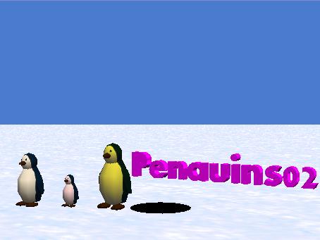
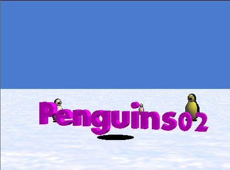
From an examination of the top-level program specifications in Figure 1, we immediately see that we will need three penguins and a hole. We also need some 3D text (see Figure 4), but the top-level specification in Figure 1 isn't very specific as to what that text should be. Therefore, before beginning the detailed program design and coding process, we will populate our world with three penguins, a hole, and a block of 3D text that shows the name of the program at the beginning of the run. (We will add another 3D text block later as we continue the development process and get closer to the end of the program.)
Will color, resize, and set the opacity of penguins manually
By default, all the penguin objects in Alice look alike. Therefore, we will need some way to visually distinguish them from one another. For starters, we will make the papa penguin the largest, and will make the baby penguin the smallest. We will make interactive method calls to resize the penguins.
However, because a small penguin close to the camera can appear larger than a large penguin at some distance from the camera, we will also give each penguin a distinctive color by manually setting their color properties. We will cause the papa penguin to have a bit of a suntan as shown in Figure 4. The baby penguin is a little girl, so we will give her a pink tint. We won't change the color of the mama penguin.
Finally, we will set the opacity property of each penguin to 0% manually so that they will be invisible when the program starts running. (You learned how to manually set property values on objects in an earlier lesson.)
Will color, resize, and set the opacity of the hole manually
We will use a circle shape for the hole in the ice. We will manually set the color property of the hole to black. We will set its size by dragging with the mouse. We will set the opacity property of the hole to 0% manually so that it will be invisible when the program starts running.
Will set the opacity of the ground and the 3D text to 0%
We also don't want the viewer to be able to see the ground or the 3D text until just the right point in the animation, so we will set the opacity property for those two objects to 0% also.
Specification for the manual setup
Although the manual setup part of the process doesn't actually constitute program code, it is essential that it be done correctly in order for our program to be successful. Therefore, it needs to be specified in writing. Our detailed specification for the manual setup is provided in Figure 3.
Figure 3. Specification for the manual setup.
Specification for the manual setup.
|
Go ahead, do the manual setup
Create your new world as specified in Figure 3. Note that in order to get three penguin objects, you can import all three from the gallery, or you can import only one, select the copy button in the upper right portion of the screen and click on the original penguin object twice.
Setting the colors
To set the color of an object, select the object in the object tree and then select the properties tab below the object tree. Pull down the choice menu for the color property. Either select a color by its name (such as MAGENTA) or select other. If you select other, you can then select the color that you need from the large selection of colors that appear on the screen and click the OK button.
Setting the size of papa and baby
To set the papa object and the baby object to the correct sizes, manually and interactively call the resize method on each of the objects and specify the multiplicative factor for the object given in Figure 3.
Setting the size of the hole
To manually set the size of the hole, drag the papa penguin to the center of the hole and then select the resize button in the upper right portion of the screen. Drag the edge of the hole to make it slightly wider than the papa penguin object.
Don't forget the Undo button
Remember if you do something wrong, you can click the Undo button near the top of the screen to reverse what you did that was wrong.
What you should see
Once you have completed the manual portion of the setup (except for setting the opacity property of all the objects to 0%), your world should look similar to Figure 4. Note, however, that your objects will probably be in different positions which will cause them to appear to be different sizes.
Figure 4. Result of the manual portion of the initial setup.
|
|
Go ahead and set the opacity property of the objects (including the ground) to 0%. This should cause your world to appear to be empty except for the blue sky.
Setting the initial viewpoints
Because we want the program to be very repeatable, we will write program code in the method named mainSetup to align the viewpoints of all the objects, including the camera, with the viewpoint of the world. Then we will write program code to set the initial viewpoints of all the objects to known repeatable values.
The only things about the initial setup that you may not be able to match exactly are the colors of the penguins and the size of the hole. Everything else will be defined in specific numeric terms.
The program design
The next step is to begin the design of the actual program. We won't attempt to design the entire program at the outset. Rather, we will separate the design process into three levels of detail. The first level of detail in the design has already been accomplished. That involved creating a program organization and specifying the names of the methods that make up the program as shown in Figure 2 (although additional methods can be added later if needed).
The second level of design detail
The second level of detail in the design will require us to specify the gross behavior of each of the methods named in Figure 2. During this cycle, we will specify the behavior of each method at a level of detail that is just sufficient to make it possible for us to run the world and to confirm that it does comply with the program organization shown in Figure 2.
Two examples
As a first example, referring back to Figure 2, the main method must call the following methods in the proper order, and those methods must behave in such a way as to convince us that they were called in the proper order:
As a second example, referring again to Figure 2, the method named act1 must call the following methods and those methods must behave in such a way as to convince us that they were called in the proper order:
This design process must be continued until every one of the methods in Figure 2 is properly linked with its parents, and every method is designed to behave in such a way as to convince us that they are all being called in the proper order. However, at this level of design detail, there is no requirement for the methods to do anything about animating penguins.
How will we become convinced?
In order to make it possible for the methods to convince us that they are all being called in the proper order, we will temporarily put print statements in each method to identify the name of the method, as well as its indentation level in Figure 2 when the method is called.
|
When we begin writing program code, we will begin by writing the sixteen methods named in Figure 2 with the hierarchical structure show in Figure 2. Except for code in some of the methods that calls other methods, (and the print statements mentioned above), the methods will initially be empty.
The methods at the lowest level of the hierarchy, (act1Scene1Setup for example), will initially be completely empty (except for the print statements). We will come back and fill these methods in with the code required to do something useful later.
Stubs
Methods created and used in this way are often called stubs or stub methods. They simply serve as placeholders during the initial part of the program development process.
|
The time has come for us to begin writing the specifications at the second level of design detail. At this point, we are pretty sure that we know all or most of the details regarding the main method. It will serve simply to call other methods to drive the program through its execution structure. Therefore, we can write the specifications for the main method as shown in Figure 5.
Figure 5. Specification for the main method.
|
Specification for the
main method.
Call the following methods in sequence:
|
|
As you can see from Figure 5, the main method simply calls four other new methods in sequence. Select world in the object tree and click the edit button beside the main method immediately below the object tree. This should cause the main method to appear in the edit pane with the name world.main appearing in the tab at the top of the edit pane.
Go ahead and write the code for the main method as specified in Figure 5.
What's that, you say you can't write the main method?
Why not?
Oh, you say that the method named mainSetup doesn't exist yet, so you can't drag its tile into the code editor for the main method. How about that?
An important lesson
You have just learned an important lesson about computer programming using Alice. Because of the drag-and-drop paradigm used in Alice, you can't write any of the methods in the program that call other new methods unless you write the lower-level new methods first.
Therefore, if we view the hierarchy of connected methods (named in Figure 2) as a sort of organizational chart or family tree, although we usually design the method execution tree from the top down, we must write the code to implement the tree from the bottom up in Alice.
Not exactly like other programming languages
In languages such as Java and C++, we could actually write the code from the top down, but we wouldn't be able to compile that code until all the required methods are available to satisfy the dependencies among the methods that constitute the tree. Because of the drag-and-drop paradigm used in Alice, you can't even write the code without first satisfying those dependencies.
Write the methods from the right to the left
What you will need to do, therefore, is to write the methods named in Figure 2 starting on the right and working toward the left. You can write the rightmost methods because they don't call any new methods. Once you have them written, you can write the methods that call those methods, etc.
Specifications for the other methods
You saw the specifications for the main method in Figure 5. At this point in the development cycle, the specifications for all of the methods are as simple, or simpler than that shown for main in Figure 5. For example, (except for the print statements), the following methods are completely empty:
Just like the main method, the following four methods simply contain calls to other methods:
Therefore, I'm not going to bore you by presenting and discussing program specifications for the fifteen methods in the two lists shown above. I will point out however, that later on we will be writing detailed specifications for the eleven methods in the first list, and those methods will no longer be empty.
|
To write each of the fifteen new methods, select world in the object tree, and then click the button labeled create new method immediately below the object tree. You will then be given an opportunity to provide a name for the new method. Provide the name and click the OK button. When you do that, a new tab will appear in the edit pane that represents your new method.
|
Once you have written the eleven empty methods in the first list given above, those eleven methods will appear as tiles in the methods tab immediately below the object tree when you select world in the object tree. That will make them available to be dragged into the edit pane as you write the main method plus the four methods in the second list given above
Put a print statement in each method
As you write these methods, drag the print tile from the bottom of the screen into each method to cause the method to print the name of the method. Insert spaces ahead of each method name such that the number of spaces is equal to the indentation level of the methods in Figure 2. (You can use one or more space characters for each level of indentation.)
Play your world to test your program
You can test your program by playing your world.
When you play your world at this point, you shouldn't see any animated penguins because you haven't written that code yet. However, a large white print area should appear on the Alice screen immediately below the World Running screen. It should contain the text produced by the print statements in your sixteen methods. (You may have to drag the borders of the print area up or down to expose all of the printed material.)
If you created the program skeleton correctly, the printed output should match that shown in Figure 6.
Figure 6. Printed output produced by initial version of Penguins02.
main mainSetup act1 act1Scene1 act1Scene1Setup act1Scene1Action act1Scene1Close act1Scene2 act1Scene2Setup act1Scene2Action act1Scene2Close act2 act2Setup act2Action act2Close mainClose |
What should your output look like?
If you compare Figure 6 with Figure 2, you should see a very strong resemblance between the two.
If your screen output doesn't look like Figure 6, you will need to determine the reason why (debug your program), make the corrections, and test the program again. Continue doing this until you get it right. There is no point in going beyond this point until you can successfully test your program at this level of design detail.
Congratulations, your first test was successful
You have successfully designed, coded, and tested your program at the second level of design detail. (Wouldn't it be nice if it was all that easy?)
The source code
Having created and successfully tested all sixteen methods in skeleton form, if you do the following, an output HTML file will be created that contains the source code for your program in its current state:
You can open the HTML file in any browser, and except for minor differences between browser types (and your name in place of mine), the output HTML file should match that shown in Listing 1. (Note the print statement in each method in Listing 1.)
Listing 1. Skeleton source code for the sixteen methods.
Penguins02's CodeCreated by: Dick BaldwinworldMethods
|
|||||||||||||||||||||||||||||||||||||||||||||||||||||||||||||||||||||||||||||||||||||||||||||||||||||||||||||
|
Hopefully by now, you know how to interpret the source code shown in Listing 1 and how to relate that presentation of the source code to the code in the Alice program edit pane.
Hopefully you also know how to relate the source code to the information in Figure 2. Note that the main method appears first in Listing 1, but all of the remaining methods appear in right-to-left, top-to-bottom order in Listing 1 (relative to Figure 2).
Congratulations
You have now successfully constructed the skeleton for the program, which consists of sixteen new methods. All that remains is to put some meat on that skeleton's bones by adding code to the methods to achieve the behavior described in the top-level program specifications shown in Figure 1.
The third level of design detail
The third level of design detail for this program will require us to design, write specifications for, code, test, and possibly debug each of the eleven empty methods in the first list given above. Once we have done that, the methods will no longer be empty. Rather, the behavior of the individual methods working together will cause the program to exhibit behavior that satisfies the top-level program specification presented in Figure 1.
|
This will entail aligning all of the objects to the world and setting the initial viewpoints for the penguins, the camera, and the 3D text.
Need to move the 3D text up slightly
The 3D text object must be moved up slightly. Otherwise, the portion of the letter g that is below the bottom of the other characters will be hidden because it will be below the surface of the ice. (See Figure 4 for an example of this problem.)
The hole is okay as is
The viewpoint for the hole is to remain aligned with the world, so there will be no requirement to set an initial viewpoint for the hole.
The code will be familiar
The code that we will use for this purpose is very similar to code that you saw in the earlier lesson titled "Learn to Program using Alice, Your First Alice Program" (see Resources).
The specification for the mainSetup method
Our detailed specification for the mainSetup method is presented in Figure 7.
Figure 7. Specification for the mainSetup method.
|
Specification for the mainSetup method. Perform the following actions with a time duration of zero.
|
Source code for the mainSetup method
Go ahead and edit the existing mainSetup method to cause its behavior to satisfy the specification in Figure 7. Unless I made an error, the source code for the updated version of the mainSetup method should match the source code shown in Listing 2.
Listing 2. Source code for the mainSetup method.
Penguins02's CodeCreated by: Dick BaldwinworldMethods
|
|||||||||||||||||||||||||||
If you have studied the earlier lessons in this series of tutorials, you should understand the source code in Listing 2 without further explanation.
Test your code by running the world
If you run the world as it is, you shouldn't see anything happening other than the printed material being displayed at the bottom of the World Running window.
However, if you temporarily change the opacity property of all the objects from 0% to 100% and then run the world, you should see some very rapid motion as the objects all assume their viewpoints. When all of the code in the program has been executed, the World Running window should like Figure 8. (Note that the 3D character g is correct in Figure 8.)
Figure 8. Output of mainSetup method with objects visible.
 |
You should perform this test
I suggest that you make that temporary change and perform this test just to confirm that your code is correct. If your output doesn't look like Figure 8, you will need to debug and repair your method. (Don't forget to set the opacity property for the objects back to 0% once your testing of the method is complete.)
The purpose of the act1Scene1Setup method is to:
The method specification
A specification for this method is presented in Figure 9.
Figure 9. Specification for the act1Scene1Setup method.
Specification for the act1Scene1Setup method.
Do the following concurrently:
Set the isShowing property on the 3D text to false so that it will be invisible during the remainder of the program. |
Source code listing for the act1Scene1Setup method
The source code for this method is shown in Listing 3.
Listing 3. Source code listing for the act1Scene1Setup method.
Penguins02's CodeCreated by: Dick BaldwinworldMethods
|
|||||||||||||||||||||||||||||
Nothing new and unusual
There is nothing new and unusual about the code in Listing 3, so it shouldn't require further explanation.
This method contains quite a lot of code that implements programming concepts that have not yet been covered in this series of tutorial lessons.
The primary purpose of this lesson is to teach you about the program development cycle consisting of the following steps:
Won't explain the details of the complex code
Since the purpose of the lesson is more about teaching you how to organize your program than it is about complex programming concepts, I won't explain the code in this method in this lesson. However, I will explain that code, or very similar code in future lessons.
Penguins wandering aimlessly on the ice
This method causes all three penguins to wander aimlessly on the ice for a short period of time. The total time that they wander and the path of each penguin is based on a random number generator.
Then there is a loud crashing sound and a hole appears in the ice.
All three penguins turn and face the hole.
Specification for the act1Scene1Action method
The specification for this method is presented in Figure 10.
Figure 10. Specification for the act1Scene1Action method.
Specification for the act1Scene1Action method.
|
Source code for the act1Scene1Action method
The source code for this method is shown in Listing 4.
Listing 4. Source code for the act1Scene1Action method.
Penguins02's CodeCreated by: Dick BaldwinworldMethods
|
|||||||||||||||||||||||||||||||||||||||||||||||||||||||||||||||||||||||||||||||||||||||||||||||||||||||||||||||||||||||||||||||||||||||||||||||||||||||||||||||||||||||||||||||||||||||||||||||||||||||||||||||||||||||||||||
Redundant code
This method is fairly long. As I explained in the comments, it would have been better to write a method containing the redundant code and call that method three times. However, that method would have required the use of method parameters, which is a programming concept not yet covered in this series of tutorial lessons. Therefore, I decided to keep it simple and simply to write the redundant code into the method.
Concurrent execution of program instructions
As you are already aware from previous lessons, you can cause program instructions in Alice to execute concurrently by dragging a doTogether tile from the bottom of the Alice environment and placing the program instructions in the code block associated with the doTogether tile.
The doInOrder tile
Sometimes when you cause programming instructions to execute concurrently, you need to make certain that the instructions in certain subsets of instructions execute in sequential order. This is accomplished by dragging a doInOrder tile from the bottom of the development environment and placing the subset of instructions in the code block associated with the doInOrder tile.
A variable named maxCnt
The code in Listing 4 contains a variable named maxCnt of type Number with an initial value of 0. To create a variable, click the button at the top right of the edit panel that reads create new variable and then fill in the blanks in the dialog that follows. The variable will then appear at the top of the edit panel immediately below the method signature.
To create a program instruction that begins with the name of the variable, drag the variable down and drop it at the appropriate location in the edit panel.
To use a variable internal to a program instruction, create the instruction using a placeholder value, and then drag the variable down and drop it on top of the placeholder.
Random functions
Two types of Random functions can be found by selecting world in the object tree and selecting the functions tab immediately below the object tree. You can tell by the code in Listing 4 which one you need to use for this program.
The wait, for, and if instructions
Create a wait instruction by dragging the wait tile from the bottom of the development environment into the program edit panel. Create a for instruction by dragging the loop tile up from the bottom of the development environment and dropping it in the edit panel. Create an if ... else statement by dragging the if tile up from the bottom of the development environment and dropping it in the edit panel.
The other program instructions
You should already know how to construct all of the other programming instructions in Listing 4, although you may not understand the full ramifications of all of those program instructions yet.
This is a fairly simple method. This method is used to create the transition from Scene 1 to Scene 2 in Act 1 of the animated presentation. Basically, it causes all of the objects to fade to blue after the hole appears in the ice.
Figure 11. Specification for the act1Scene1Close method.
|
Specification for the act1Scene1Close method. Cause the ground, the three penguins, and the hole to fade to blue concurrently over a time period of 2 seconds. |
Source code for the act1Scene1Close method.
The source code for this method is shown in Listing 5.
Listing 5. Source code for the act1Scene1Close method.
Penguins02's CodeCreated by: Dick BaldwinworldMethods
|
|||||||||||||||||||||
There is nothing in Listing 5 that you haven's seen several times before, so the code in Listing 5 shouldn't require further explanation.
The purpose of this method is to provide a fancy transition into the action portion of Scene 2 of Act 1. Mainly it involves some fancy camera work as indicated in the specification in Figure 12.
Figure 12. Specification for the act1Scene2Setup method.
|
Specification for the act1Scene2Setup method Make the camera face papa while he is still invisible. Make the following objects fade into view concurrently over a 2 second interval:
Zoom the camera in toward papa by 5 meters and do a barrel roll at the same time. Execute the zoom during a 5 second interval. Execute the roll during a 4 second interval. Make the camera do a complete circle around papa, facing papa all of the time, and spiraling away from papa by 5 meters. Do all of these things at the same time, and make them happen over a five second interval. Turn the camera to face the hole. |
Source code for the act1Scene2Setup method
The source code for this method is presented in Listing 6.
Listing 6. Source code for the act1Scene2Setup method.
Penguins02's CodeCreated by: Dick BaldwinworldMethods
|
||||||||||||||||||||||||||||||||||||||||||||||
Although the code in Listing 6 uses some methods that haven't previously been used in the same way before in this series of tutorials, all of the code in Listing 6 consists of straightforward method calls and shouldn't require further explanation.
Rotation around a second object
There is one very interesting aspect to the code in Listing 6, however. By default, the turn method, when turning RIGHT or LEFT, causes the object to rotate around its own green axis. (I discussed the red, green, and blue axes belonging to an object in an earlier lesson. See Resources.) However, there is no requirement that the object rotate around its own green axis. By setting the asSeenBy parameter to another object, you can cause the first object to rotate around the green axis belonging to the other object.
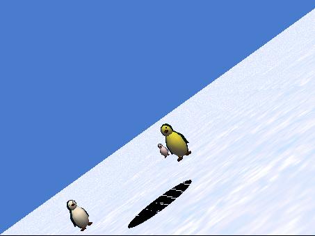
Fancy camera work
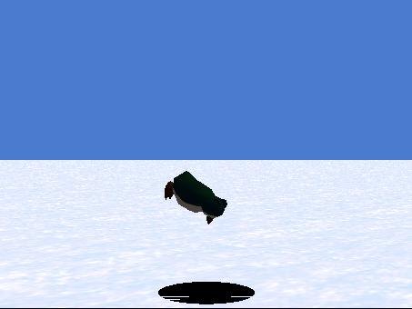
There is some fancy camera work in this method, (such as that shown in Figure 13), where the camera is zooming in toward papa penguin and executing a barrel roll at the same time.
Figure 13. Camera zooming in and executing a barrel roll.
|
|
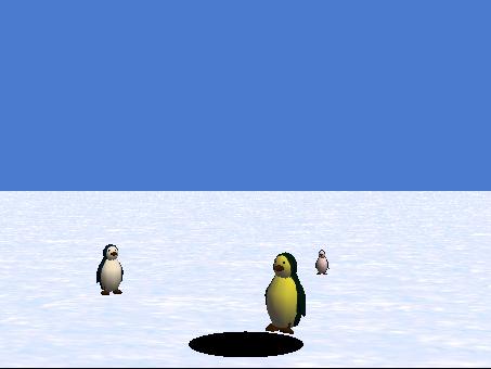
This is the main show. This is what everyone came to the theatre to see. In this method, papa penguin walks to the edge of the hole and peers in, deciding to take a swim as shown in Figure 14.
Figure 14. Papa penguin looking into the hole.
|
|
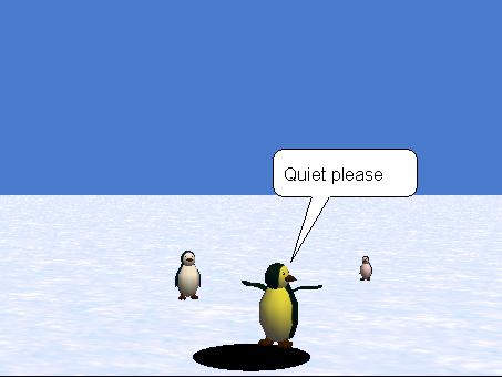
Pretending to be an Olympic diver
He also decides to show off as he pretends to be an Olympic diver (as shown in Figure 15) where he raises his wings and asks the crowd for quiet.
Figure 15. Papa penguin showing off.
|
|
Diving in head first
After showing off a little, he dives in head first as shown in Figure 16. Note that the camera is circling around papa penguin as he executes the dive.
Figure 16. Papa penguin diving head first into the hole.
|
|
Completing the dive
Finally Figure 17 shows papa penguin completing his dive with just his feet sticking out of the water. This results in a loud splash sound.
Figure 17. Papa penguin with just his feet sticking out of the water.
|
|
Speeding up the execution
As you continue to develop your program, it gets longer and longer. You may get tired of watching the first part of the animation each time while you are waiting to get to the new material. There are at least two ways to speed up the early portions of the animation to alleviate that problem.
Using the slider
First, there is a slider at the top side of the World Running screen that allows you to increase the speed by as much as a factor of ten. This is useful for moving rapidly through portions of the animation that you have already tested and that you are happy with.
Selectively disabling code
Second, you can selectively disable and enable blocks of code, including method calls, by right-clicking on the block's handle and selecting disable or enable in the popup menu that appears. This can also be very useful for temporarily disabling the execution of portions of the animation that you have already tested and that you are happy with.
Source code for the act1Scene2Action method
The source code for this method is shown in Listing 7.
Listing 7. Source code for the act1Scene1Action method.
Penguins02's CodeCreated by: Dick BaldwinworldMethods
|
||||||||||||||||||||||||||||||||||||||||||||||||||||||||||||||||||||||||||||||||||||||||||||||||||||||||||||||||
Although Listing 7 contains some code that I haven't explained before, if you have been studying all of the lessons in this series, you should be able to figure out what is going on in Listing 7 on the basis of the comments, the method names, etc.
This method contains a quick and dirty close for Act 1 Scene 2. The camera simply moves backwards away from the hole by 100 meters, causing the mama penguin and the baby penguin to appear as very small dots on the screen.
This code was so simple that it didn't need to be in a method of its own. However, I decided to leave the method intact in case you would like to add code to the method to provide a more impressive closing animation for Act 1 Scene 2.
The specification for the method
The specification for the method is almost trivial, but I will go ahead and write it down in Figure 18 for consistency.
Figure 18. Specification for the act1Scene2Close method.
|
Specification for the act1Scene2Close method.
Move the camera backwards away from the hole by 100 meters over a five second interval. |
Source code for the act1Scene2Close method
The source code for this method is presented in Listing 8.
Listing 8. Source code for the act1Scene2Close method.
Penguins02's CodeCreated by: Dick BaldwinworldMethods
|
|||||||||
Note that Act 2 is not subdivided into scenes. Therefore, Act 2 consists of the follow segments:
At the end of Act 1, the camera was 100 meters out in space. This setup method causes the camera to spiral in from space toward the mama penguin. After the camera finishes the trip in from space, it turns to face the hole. This was done in an attempt to make certain that both the mama penguin and the baby penguin are in the camera's viewfinder.
Specification for the act2Setup method
The specification for this method is shown in Figure 19.
Figure 19. Specification for the act2Setup method.
|
Specification for the act2Setup method. Point the camera at the mama penguin. Cause the camera to spiral toward mama, rolling to the right by 3 revolutions, during a 5-second interval. Turn the camera to face the hole. |
Note that the difference in behavior between the pointAt method and the turnToFace method is very subtle. I won't attempt to explain that difference in this lesson. However, I have explained the difference, as well as the behavior of all twenty primitive methods in Appendix A (see Resources).
The source code for the act2Setup method
The source code for this method is shown in Listing 9.
Listing 9. Source code for the act2Setup method.
Penguins02's CodeCreated by: Dick BaldwinworldMethods
|
||||||||||||||||||||||||||||||||
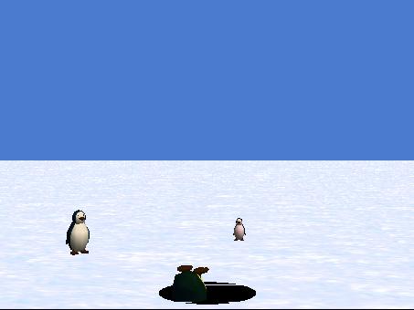
In this method, the mama penguin and the baby penguin walk to the edge of the hole and look down into the hole. Except for the display of a 3D "The End" message in the next method, that is the end of the action and the end of the animated presentation for this program.
Specification for the act2Action method
The specification for this method is presented in Figure 20.
Figure 20. Specification for the act2Action method.
|
Specification for the act2Action method. Cause the mama penguin and the baby penguin to concurrently walk to the edge of the hole and to turn their heads to look down into the hole. |
Source code for the act2Action method
The source code for this method is presented in Listing 10.
Listing 10. Source code for the act2Action method.
Penguins02's CodeCreated by: Dick BaldwinworldMethods
|
||||||||||||||||||||||||||||||||||||||||
Fairly complex arithmetic expressions
The code in this method uses a pair of fairly complicated arithmetic expressions to make certain that the penguins don't walk to the middle of the hole and stand there in thin air above the hole. The arithmetic expressions are used to compute the distance from each of the penguins to the edge of the hole.
The getWidth method returns the diameter of the circle that represents the hole. Beyond that, if you are familiar with algebraic expressions, you should be able to figure out exactly what is going on in this method but you may need to write it out on paper and group the pairs of parentheses.
The next thing that happens when the program is run is that the method named mainClose gets called to provide the closing for the entire program. I didn't have anything special in mind for a transition from Act 2 to the final closing. Therefore, I left this method empty. However, I decided to leave its skeleton intact as a placeholder just in case you would like to put some code into it. Otherwise, feel free to remove this method from the overall program structure.
We are just about finished. We have one more method to design, specify, code, and test. This method will post a 3D text block on the screen announcing the end of the animated presentation.
Need to create the 3D text block
Before you begin with this method, you need to go to the gallery and add a new 3D text object to the world. The object should contain the text "The End".
We could have added this object during the initial manual setup. However, I didn't do so because I wanted to demonstrate that you can add new objects to the world during the development process if you need to.
Go ahead and add the new object. Set its color property to MAGENTA to match the opening text. Make it totally invisible by setting its isShowing property value to false.
Behavior of the mainClose method
When Act 2 ended, the mama penguin and the baby penguin were standing at the edge of the hole looking down into the hole.
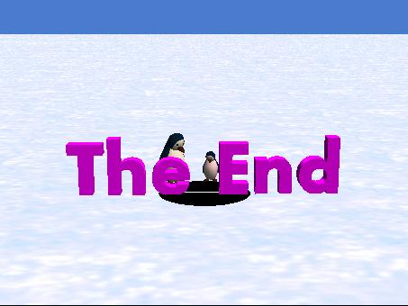
This method causes the 3D text block showing The End to zoom in from the depths of the screen, doing a little rotation along the way and to park above the hole in front of the penguins, who are still looking down into the hole. At that point, the method and the program have nothing more to do, so there is no more action on the screen.
Screen shot at the end of the animation
Figure 21 shows a screen shot of the end of the animation.
Figure 21. Screen shot at the end of the animation.
|
|
Specification for the mainClose method
The specification for this method is presented in Figure 22.
Figure 22. Specification for the mainClose method.
|
Specification for the mainClose method Do the following actions in order with a duration of 0 seconds for each action:
Do the following actions concurrently with a duration of 3 seconds for each action:
|
Source code for the mainClose method
The source code for this method is presented in Listing 11.
Listing 11. Source code for the mainClose method.
Penguins02's CodeCreated by: Dick BaldwinworldMethods
|
||||||||||||||||||||||||
There is nothing new or different in this code, so it shouldn't require further explanation.
I encourage you to use the code that I have provided in this lesson to write and play the program. If you don't want to write the code, you can download an executable copy (see Resources). Experiment with the program, making changes and observing the results of your changes. Above all, have a little fun in the process.
A step-by-step tutorial
In this lesson, I walked you step-by-step through the design, specification, coding, testing, and debugging of a complete Alice animation program.
A two-act play
The presentation is subdivided into two acts and several scenes, with some special effects used to emphasize the transitions between scenes.
Emphasizes the design and organization
The emphasis in this lesson was on the design and organization of a computer program. The actual code that implements the program includes some important programming concepts that I haven't previously covered in this series of tutorials. In some of those cases, I deferred the explanation of the code to future lessons that concentrate on those concepts.
I will tackle the topic of value-returning functions in the next lesson.
The lab project for this lesson is to follow the instructions given in the lesson to write, test, debug (if necessary), and run the program named Penguins02. Feel free to add a few creative touches of your own to the behavior of the program. However, for consistency with the other lessons in the series, you should name the program Alice130LabProjA instead of Penguins02.
Save your world in a file named Alice130LabProjA.a2w and be prepared to deliver it to your instructor in whatever manner the instructor specifies.
Make certain that your preferences are set to Java Style in Color.
Select Export Code For Printing... on the File menu and save your source code in a file named Alice130LabProjA.html. Also be prepared to deliver this file to your instructor in whatever manner the instructor specifies.
View a movie of the lab project
You can download and play a small, low-quality movie of my version of the lab project as it being executed from the Resume button (see Resources). This movie was designed to give you a rough idea of how your program should behave. The movie was purposely recorded in low-quality wmv format in a small window in order to reduce the file size and hence reduce the download time.
Because of the low quality of the movie, the execution of your program should provide much smoother animation than the movie, and should be much less grainy than the movie. Also, because of the low quality of the movie, the timing in the movie doesn't necessarily match the duration times specified for the lab project.
I attempted to synchronize the beginning of the recording with the beginning of the program execution by starting, then quickly pausing, and then resuming the execution. If you watch closely, when the movie starts running, you will see the mouse pointer click the Resume button, and the movie will show one complete pass through the program.
You should view this movie in its original size. If you allow the media player to enlarge it, the quality will be very poor.
Copyright 2007, Richard G. Baldwin. Faculty and staff of public and private non-profit educational institutions are granted a license to reproduce and to use this material for purposes consistent with the teaching process. This license does not extend to commercial ventures. Otherwise, reproduction in whole or in part in any form or medium without express written permission from Richard Baldwin is prohibited.
Richard has participated in numerous consulting projects and he frequently provides onsite training at the high-tech companies located in and around Austin, Texas. He is the author of Baldwin's Programming Tutorials, which have gained a worldwide following among experienced and aspiring programmers. He has also published articles in JavaPro magazine.
In addition to his programming expertise, Richard has many years of practical experience in Digital Signal Processing (DSP). His first job after he earned his Bachelor's degree was doing DSP in the Seismic Research Department of Texas Instruments. (TI is still a world leader in DSP.) In the following years, he applied his programming and DSP expertise to other interesting areas including sonar and underwater acoustics.
Richard holds an MSEE degree from Southern Methodist University and has many years of experience in the application of computer technology to real-world problems.
-end-